The final is a CD that contains the following:
1 A folder containing the completed House Project. Read over the assignment to make sure you have completed all the requirements.
2 A folder containing the completed Surface Project. Read over the assignment to make sure you have completed all the requirements.
3 A folder containing all tutorials.
4 A folder containing studio work modeled in Maya, and/or rendered in Maxwell.
5 Extra stuff/credit. There were three extra credit assignments: 1 the notes from the scripting seminar, with an example modeled. 2 A Erwin Hauer screen modeled and rendered. 3 A rendered of the house project. I will also except other completed studies and projects modeled in Maya in the last semester. And when I say completed I mean don't give me a bunch of crap.
The file is due in class on Saturday April 24th at 9:30 am. Do not leave anything for me in my box or in the office, because I will not see it, and you will get a BIG FAT F on the final.
Saturday, April 18, 2009
Saturday, April 4, 2009
Final Tutorial


 1.Create a NURBS circle, radius = 1, scale the circle to 50x50.
2.Scale the CV to square off the circle.
3.Change the frames from 24 to 200.
4.In the channel editor go to channels > key all circle at 1. A red line should appear at the number one on the time slider.
5.Move the time slider to 200. Translate the circle to 200 on the z-axis. In the channel editor go to channels > key all the circle at 200. A red line should appear at the number 200 on the time slider.
6.In the animation menu go to animation> Create Animation Snapshot click on the box.
7.In the Create Animation Snapshot window select Time Slider, change the increments to 12.00 and select Fast Up Date on Demand.
8.A snap shot group should appear in the options window. Create 5 layers: structure, glass, slabs, snapshot and circle. Put the stuff on the right layers.
9.Turn off the snapshot layer. Select the circle. Go to the surface menu. Select surface>planer click on the box.
10.Select polygons, quads, standard fit, and turn the sliders on the bottom of the window all the way down.
11.Extrude the polygon surface .337, use the “local translate z” for an exact measure.
12.Select the extruded polygon surface. In the animation menu go to animation> Create 13.Animation Snapshot click on the box.
14.In the Create Animation Snapshot window select Time Slider, change the increments to 12.00 and select Fast Up Date on Demand.
15.Put the snapshot in the slab layer and turn it off. Open the layer with the snap shot of circles.
16.In the surface menu, go to surface>loft, click on the box. Select NURBS and make the section span= 2
17. Put lofted surface on glass layer. Close snapshot layer.
18.Select the lofted surface. In the surface menu go to edit curve>duplicate surface curve.
19.In the side view, select the horizontal curves and delete them. (Or put them on a layer and turn them off—you can always use them for something else.)
20.Create a NURBS circle, scale the circle to .337, and extrude the circle along the vertical curves (Just like tutorial 3).
21.Put all those extruded surfaces and vertical curves on the layer structure.
22.Turn all the layers on. In the options window select the original circle. Move the time slider all the way to 200.
23.Scale the circle on the x to 30.24.Rotate it on the z 4525.In the channel editor go to channels > key all
26.Put a plane underneath the tower and render it.
Surface Project
Surface Project.
Surface Project Due 04/18/08
For the next project you will design a surface using the various techniques we covered in class
The Parameters:
Create 3 to 5 polygon objects with the identical number of faces. These should be a reasonable simple object, derived from your inspirational image.Use the ‘blend shape’ tool to morph these object into one another in various no less than 5 iterations, animate the blends and create animation snapshots of the blends.
With no less than 3 of these blended iterations create a formal gradient across two dimensions- with no less than 25 individual shapes. Attach these shapes by extruding the faces, deleting the end faces, and merging the individual vertexes to the next shape over.
In this project you must use various deformers, such as the clusters, lattice, joints, with the use of the non-linear deformers (bend, wave, sign…)This project should be thought as an architectural pavilion- it should have a circulation, and loose program.Use a ground plan and 3D person to give scale to the project.
Deliverables:
1. The inspiration and intention of your project.
2. Process, At least 5 print screens of the process, with a brief explanation for each.
3. 3 perspectives of the pavilion. Each perspective should be shown as a 1 wire frame print screen, 1 shaded print screen, 1 Maya software rendering using the GI system, 1 mental ray rendering using ambient occlusion, 1 vector rendering, and 1 maxwell rendering. 18 images in all in a PowerPoint presentation- with one image per page, full bleed, no text.
4. The Maya file.
Saturday, February 28, 2009
RENDERING TUTORIAL
FIRST CREATE A FILE ON YOUR DESKTOP CALLED MAYA RENDERINGS
IN MAYA GOTO FILE>PROJECT>SET AND SELECT THE MAYA RENDERING FILE
MAYA SOFTWARE
MENTAL RAY

MAXWELL RENDERING
 VECTOR RENDERING
 MAYA SOFTWARE:
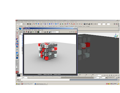
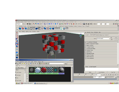
Open the cube tutorial
Make a new cube and scale it on the x and y to 50’ by 50’, use it for a plane under the cubes
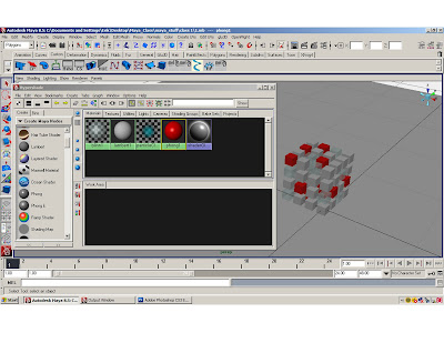
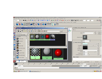
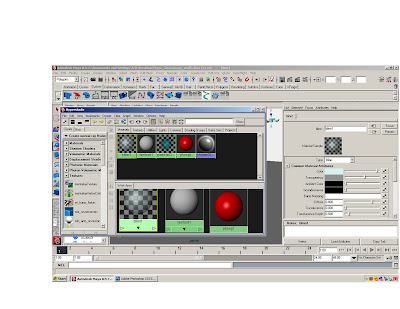
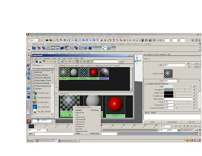
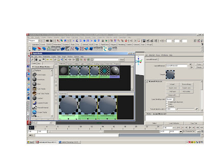
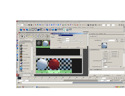
Open the hypershader and create a phong, blinn and lambert.
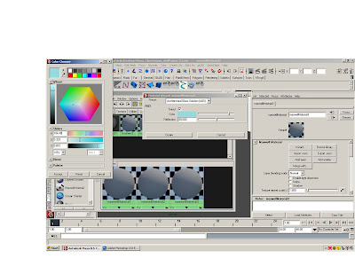
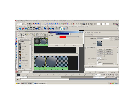
Adjust the colors and transparency of materials.
Apply the materials randomly to the cubes.
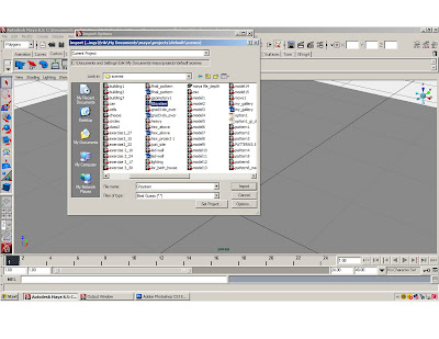
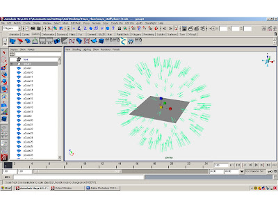
Import the GI lighting system.
File>import>GI lighting system.
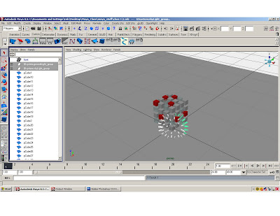
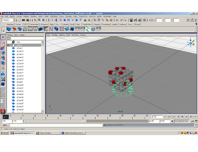
Select the imported GI lighting system groups in the options window and press ctrl G to group the GI Lights. Scale the lights out and surround the cubes.
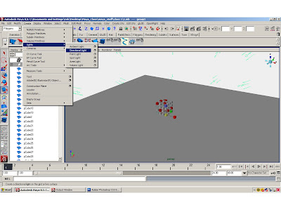
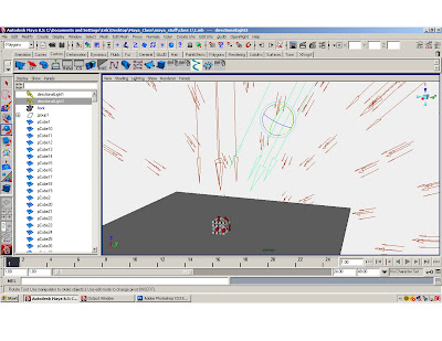
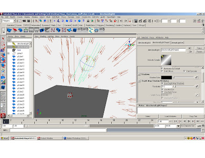
Create a directional light, scale it move it up and duplicate it. Move the duplicate light over and rotate it towards the cubes. Go to the attribute editor of the duplicate directional light, scroll down and open the shadow tab. Click on the ‘use depth map shadows’. Adjust the resolution to over 512.
Select the perspective camera in the option window, open the attribute editor for the camera, and open the environment tab. Adjust the color to white.
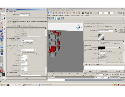
Open the render settings window.
Under the ‘common’ tab adjust the image size to 640x480, and adjust the resolution to 200.
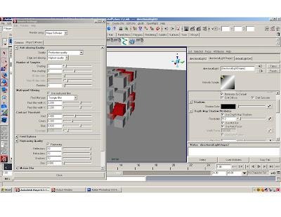
Under the Maya software tab, change the “quality’ to “production quality”, open the ray trace tab and click the ray trace box.
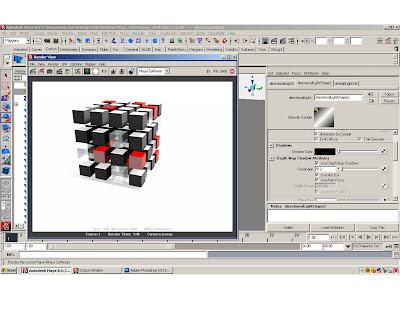
Render the scene
When the render is finished, save the render as a jpeg.
Save the file.
AMBIENT OCULSSION:
Open the cube tutorial and make three new materials.
Adjust the color and transparency of materials.
Select the perspective camera in the option window, open the attribute editor for the camera, and open the environment tab. Adjust the color to white.
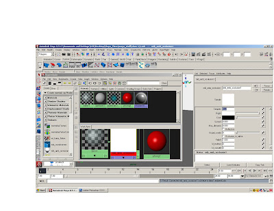
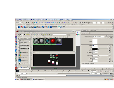
Right click the mouse on “crate maya node” box and select “create mental ray node”.
Open the “textures” tab, and middle click the mouse on “mb_amb_occlusion”, hold down the middle button, and drag over to one of the materials. Select “ambient color” from the list. Double click on the “mb_amb_occlusion”, and in the attribute editor increase the samples to 512. Repeat for all materials.
Apply the materials to the cubes.
Open the render settings window.
In the “render using:” box select “mental ray”
Under the ‘common’ tab adjust the image size to 640x480, and adjust the resolution to 200.
Click on the Mental Ray tab, and change the production preset box to “Production”
Render
Save render as jpeg.
Save file.
Maxwell rendering:
Open the cube tutorial
Make a new cube and scale it on the x and y to 50’ by 50’, use it for a plane under the cubes
Go to window> settings and preferences > plug-in manager and click on all the boxes, and click refresh.
Open the hypershader and create three Maxwell materials.
Double click on the Maxwell materiasl and use the wizard to create a glass and car paint and plastic.
Apply the materials to the cubes.
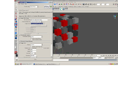
Open the render settings window.
In the “render using:” box select “Maxwell”
Under the ‘common’ tab adjust the image size to 640x480, and adjust the resolution to 200.
Click on the “Maxwell” tab.
Increase the time to 20 minutes
Increase the samples to 1000
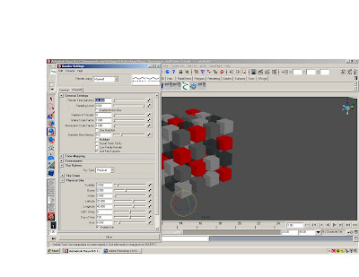
Click on the “Environment” tab.
Click on sky options
The physical sky will create a realistic sky, and is controlled with the various controls.
At minimum adjust the hour and click on the enable sun.
The sky dome will create a blank background-- adjust the color.
Render the scene.
The Maxwell render window will start up. When it starts you can go back to the maya file and continue working.
When the Maxwell rendering is finished, save the file as a jpeg.
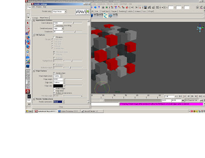
VECTOR RENDERING:
Select the perspective camera in the option window, open the attribute editor for the camera, and open the environment tab. Adjust the color to white.
Open the render settings window and select Maya Vector in the render using box.
In the image format box, select “encapsulated postscript (eps)”.
Change the image size to the 320x240 preset, in the preset window.
Click on the Maya Vector tab.
Change the “Detail level preset” window to “high”
Click the fill objects box off
Click the include edges box on
Change the “Render optimization” box to “Good”
Render the scene.
In Illustrator or Photoshop overlap the vector on other renders
Go to window > Rendering Editors > Mental ray > Approximation Editor
With the Approx. Editor window open, select the object you wish to ‘smooth’ press the Create button under the Subdivision (Poly and Sub .D sufraces) section.
IN MAYA GOTO FILE>PROJECT>SET AND SELECT THE MAYA RENDERING FILE
MAYA SOFTWARE


MENTAL RAY


MAXWELL RENDERING


 VECTOR RENDERING

 MAYA SOFTWARE:
Open the cube tutorial
Make a new cube and scale it on the x and y to 50’ by 50’, use it for a plane under the cubes
Open the hypershader and create a phong, blinn and lambert.
Adjust the colors and transparency of materials.
Apply the materials randomly to the cubes.
Import the GI lighting system.
File>import>GI lighting system.
Select the imported GI lighting system groups in the options window and press ctrl G to group the GI Lights. Scale the lights out and surround the cubes.
Create a directional light, scale it move it up and duplicate it. Move the duplicate light over and rotate it towards the cubes. Go to the attribute editor of the duplicate directional light, scroll down and open the shadow tab. Click on the ‘use depth map shadows’. Adjust the resolution to over 512.
Select the perspective camera in the option window, open the attribute editor for the camera, and open the environment tab. Adjust the color to white.
Open the render settings window.
Under the ‘common’ tab adjust the image size to 640x480, and adjust the resolution to 200.
Under the Maya software tab, change the “quality’ to “production quality”, open the ray trace tab and click the ray trace box.
Render the scene
When the render is finished, save the render as a jpeg.
Save the file.
AMBIENT OCULSSION:
Open the cube tutorial and make three new materials.
Adjust the color and transparency of materials.
Select the perspective camera in the option window, open the attribute editor for the camera, and open the environment tab. Adjust the color to white.
Right click the mouse on “crate maya node” box and select “create mental ray node”.
Open the “textures” tab, and middle click the mouse on “mb_amb_occlusion”, hold down the middle button, and drag over to one of the materials. Select “ambient color” from the list. Double click on the “mb_amb_occlusion”, and in the attribute editor increase the samples to 512. Repeat for all materials.
Apply the materials to the cubes.
Open the render settings window.
In the “render using:” box select “mental ray”
Under the ‘common’ tab adjust the image size to 640x480, and adjust the resolution to 200.
Click on the Mental Ray tab, and change the production preset box to “Production”
Render
Save render as jpeg.
Save file.
Maxwell rendering:
Open the cube tutorial
Make a new cube and scale it on the x and y to 50’ by 50’, use it for a plane under the cubes
Go to window> settings and preferences > plug-in manager and click on all the boxes, and click refresh.
Open the hypershader and create three Maxwell materials.
Double click on the Maxwell materiasl and use the wizard to create a glass and car paint and plastic.
Apply the materials to the cubes.
Open the render settings window.
In the “render using:” box select “Maxwell”
Under the ‘common’ tab adjust the image size to 640x480, and adjust the resolution to 200.
Click on the “Maxwell” tab.
Increase the time to 20 minutes
Increase the samples to 1000
Click on the “Environment” tab.
Click on sky options
The physical sky will create a realistic sky, and is controlled with the various controls.
At minimum adjust the hour and click on the enable sun.
The sky dome will create a blank background-- adjust the color.
Render the scene.
The Maxwell render window will start up. When it starts you can go back to the maya file and continue working.
When the Maxwell rendering is finished, save the file as a jpeg.
VECTOR RENDERING:
Select the perspective camera in the option window, open the attribute editor for the camera, and open the environment tab. Adjust the color to white.
Open the render settings window and select Maya Vector in the render using box.
In the image format box, select “encapsulated postscript (eps)”.
Change the image size to the 320x240 preset, in the preset window.
Click on the Maya Vector tab.
Change the “Detail level preset” window to “high”
Click the fill objects box off
Click the include edges box on
Change the “Render optimization” box to “Good”
Render the scene.
In Illustrator or Photoshop overlap the vector on other renders
TO RENDER A SMOOTHED POLYGON:
USE MAXWELL
OR IN MENTAL RAY
Go to window > Rendering Editors > Mental ray > Approximation Editor
With the Approx. Editor window open, select the object you wish to ‘smooth’ press the Create button under the Subdivision (Poly and Sub .D sufraces) section.
Subscribe to:
Posts (Atom)